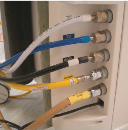
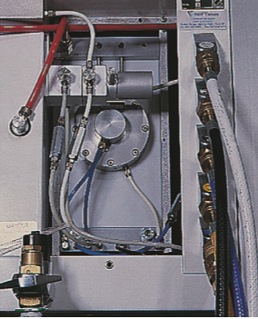
Medical gas supply-
The wall fitting consists of Shrader socket with an indexed collar
The wall fitting consists of Shrader socket with an indexed collar
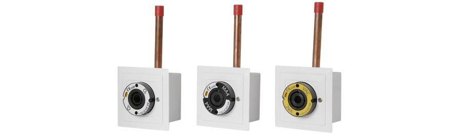
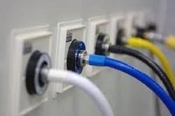
Medical gas pipelines are non-interchangeable, non-compressible, colour coded, and flexible, fitted to the machine with a NIST-UK (non interchangeable screw thread) or DISS-USA (diameter indexed safety system)
Pipeline pressure should be 4 bar(400kPa)
Pipeline pressure should be 4 bar(400kPa)
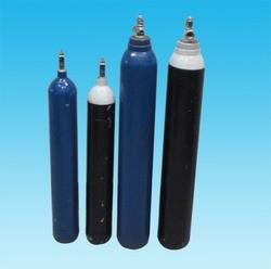
Cylinders are made of molybdenum steel or aluminium alloy to resist high pressures; should be turned on slowly to avoid a sudden rise of pressure in the machine; must be turned on fully to reduce fall in pressure as they empty; turning off should be without excess force to prevent damage to valve settings.
Oxygen is in the form of a gas and is pressurised to to 137 bars(13700kPa), pressure decreases linearly as the gas is consumed.
Nitrous oxide is in liquid form and the measured pressure of 51.6 bars(51600kPa) decreases only after 75% of the liquid has vaporised.
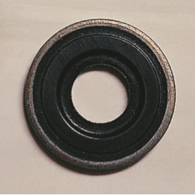
A Bodok seal is interposed between the cylinder and yoke to prevent leaks
Oxygen is in the form of a gas and is pressurised to to 137 bars(13700kPa), pressure decreases linearly as the gas is consumed.
Nitrous oxide is in liquid form and the measured pressure of 51.6 bars(51600kPa) decreases only after 75% of the liquid has vaporised.
A Bodok seal is interposed between the cylinder and yoke to prevent leaks
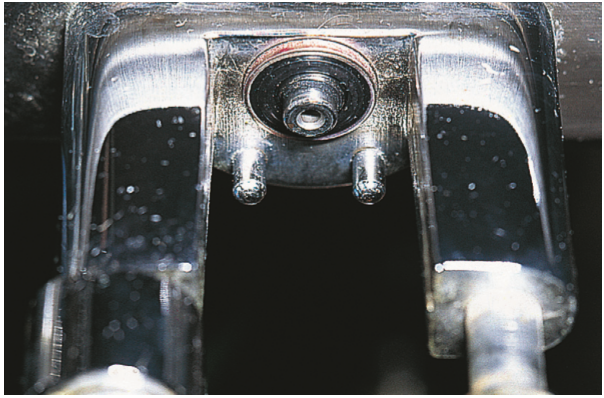
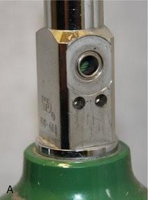
A non interchangeable gas supply is ensured by:
1) colour coding
2) Pin indexing
1) colour coding
2) Pin indexing
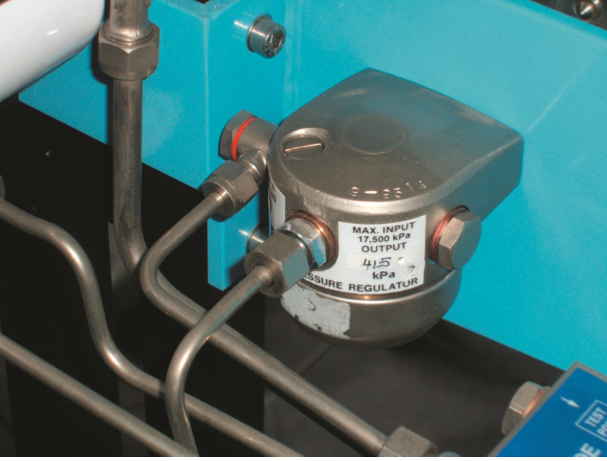
Pressure reducing regulators reduce cylinder pressure to a safe level of 4 bar(400kPa) and maintain it constant despite reduction in the cylinder pressure during use.
Oxygen supply failure alarm gives an audible alarm for 7sec when the oxygen pressure falls to 2 bar(200kPa).
It cuts off flow of other gases.
It cuts off flow of other gases.
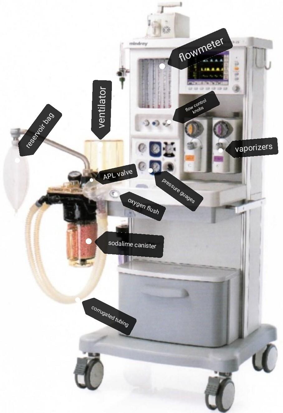
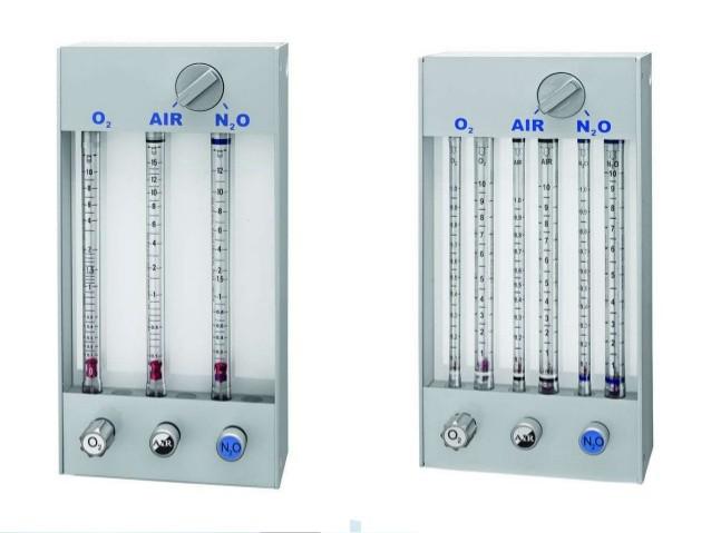
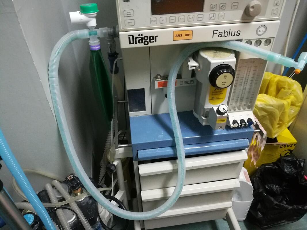
Flowmeters consist of tapered tube, typically made of glass, with a bobbin inside that is pushed up by gas flow and pulled down by gravity. As flow rate increases, greater viscous and pressure forces on the bobbin cause it to rise until it becomes stationary at a location in the tube that is wide enough for the forces to balance.
The calibration is non linear because the flowmeter tube increases in diameter from bottom upwards, conically tapered.
Each tube is calibrated at 20^C specifically for one gas only, and is not interchangeable.
Oxygen bleed is a flow of 250ml of O2/min when the machine is switched on.
Anti hypoxic devices link the O2 and N2O flow control needle valves to ensure that N2O reduces proportionately to ensure a minimum FiO2 of 0.25.
The bobbin is specific for the tube and should rotate freely; fins cut into its upper surface make it spin easily and a white spot shows rotation; a gold/tin coating prevents it from sticking due to static electricity; the upper margin of the bobbin indicates the flow rate.
Flow control knobs are colour coded and labelled with the name of the gas; the oxygen control knob is unique, it is the largest and is fluted and octagonal in profile,and may project out more,to be easily recognized by sight and touch.
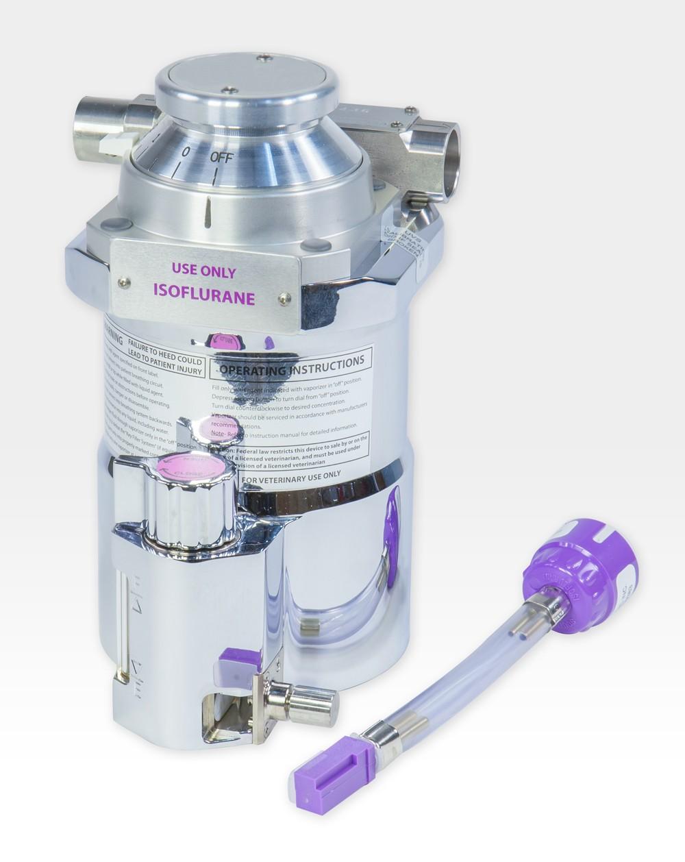
Vaporizers have an interlock mechanism and the key filling system
Oxygen flush line commences before the flow meters and bypasses the vaporizes, the flow should be more than 35L/min and less than 75L/min
Safety valves, one before the flow meter (releasing at 800kPa) and one on the back bar (blow off at 40kPa) protect the flow meter and vaporizer from high pressures.
Expiratory valves in the breathing system limit the pressure to 6kPa to protect the patient from barotrauma (Maximum pressure setting in APL valve- 60cmH2O)
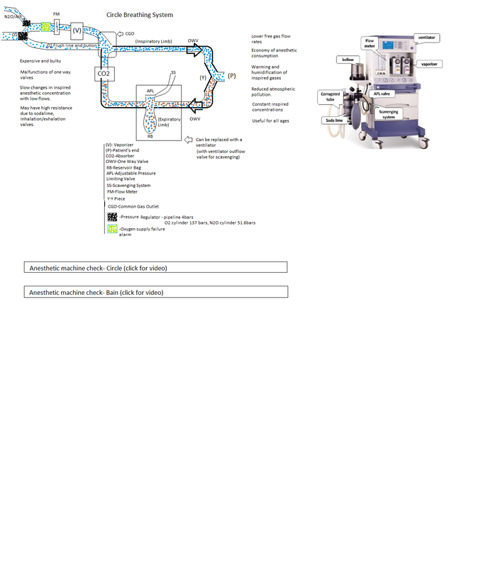
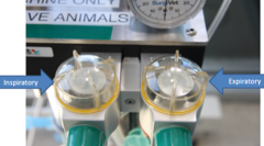
One way (unidirectional) inspiratory and expiratory valves are of the turret type, in which the pressure generated by the patient's breathing causes the disc to rise and allows gas to pass in one direction only. Most have a transparent dome so that the operation of the valve may be observed.
Incompetent inspiratory or expiratory valves will reduce the efficiency of gas circulation and result in rebreathing and consequent CO2 retention.
Safety valves, one before the flow meter (releasing at 800kPa) and one on the back bar (blow off at 40kPa) protect the flow meter and vaporizer from high pressures.
Expiratory valves in the breathing system limit the pressure to 6kPa to protect the patient from barotrauma (Maximum pressure setting in APL valve- 60cmH2O)
One way (unidirectional) inspiratory and expiratory valves are of the turret type, in which the pressure generated by the patient's breathing causes the disc to rise and allows gas to pass in one direction only. Most have a transparent dome so that the operation of the valve may be observed.
Incompetent inspiratory or expiratory valves will reduce the efficiency of gas circulation and result in rebreathing and consequent CO2 retention.
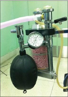
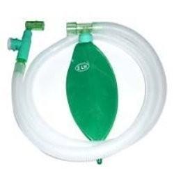
Function of the reservoir bag
1)A reservoir for fresh gas
2)A device which makes manual ventilation possible
3)A visual monitor for rate and depth of respiration
4)A safety device, preventing high pressures in the system due to its special compliant properties which allows expansion to prevent increase in pressure.
1)A reservoir for fresh gas
2)A device which makes manual ventilation possible
3)A visual monitor for rate and depth of respiration
4)A safety device, preventing high pressures in the system due to its special compliant properties which allows expansion to prevent increase in pressure.
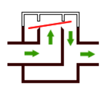
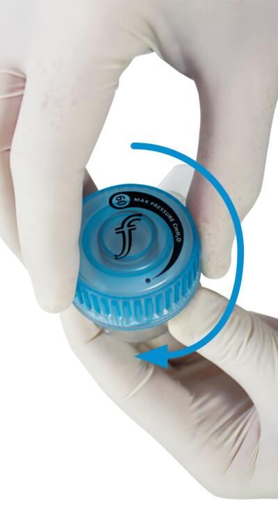
Adjustable pressure limiting valve(APL valve) is one-way, adjustable, spring-loaded valve which allows gases to escape when the pressure in the breathing system exceeds the valve's opening pressure.
During spontaneous ventilation the patient generates a positive pressure during expiration,causing the valve to open.
During positive pressure ventilation, a controlled leak is produced in inspiration by adjusting the valve dial, allowing control of the patient's airway pressure.
During spontaneous ventilation the patient generates a positive pressure during expiration,causing the valve to open.
During positive pressure ventilation, a controlled leak is produced in inspiration by adjusting the valve dial, allowing control of the patient's airway pressure.
In Double-canister absorbers the top canister is exposed to the expired gas first and removes most of the CO2. Any remaining CO2 is then removed by the bottom canister. When the top canister is exhausted, the absorbant is discarded, the bottom canister is placed in the top position and a canister with fresh absorbent is inserted underneath it. However, these absorbers are bulkier, heavier and more expensive than single canister models.
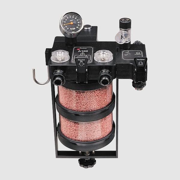
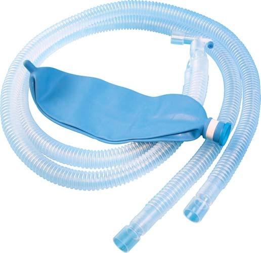
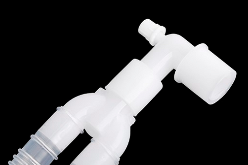
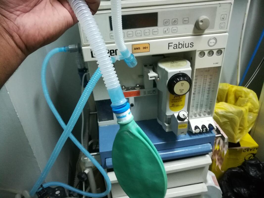
The body of the absorber is connected to the patient by means of inspiratory and expiratory tubes and a Y-piece.
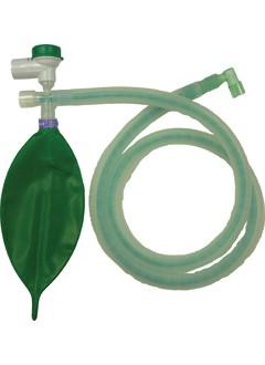
Large bore, non-rigid breathing and usually corrugated (conducting) tubes, typically made of rubber or plastic
Corrugations increase flexibility and resistance to kinking
Clear plastic tubes are more lightweight, absorb less halogenated agents, have a lower compliance than rubber tubes and allow visualization of the interior of the tube.
Act as a reservoir in certain systems.
Provide a flexible, low resistance, light-weight connection from one part of the system to another.
Have some distensibility but not enough to prevent excessive pressures from developing
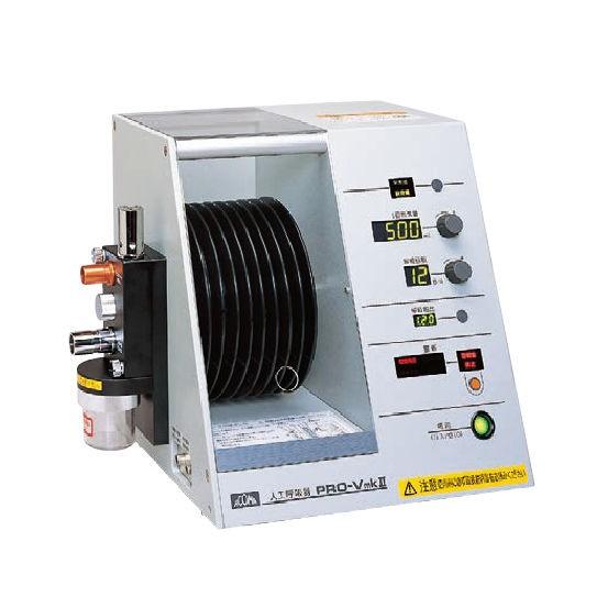
Ventilators are two types
1) Gas driven
1) Gas driven
Are not recommended except with pipelines as their oxygen requirements are high.
If there are leaks the bag does not reach the top of the bottle.
If there is an obstruction the bag does not come down adequately.
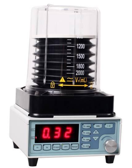
2) Electrically driven
If there are leaks the bag does not reach the top of the bottle.
If there is an obstruction the bag does not come down adequately.
2) Electrically driven
These have a piston system which is not visible.
The only evidence of leaks or increased pressures is the airway pressure in the monitor.
Pressure limiting valves should be set at 40cmH2O to prevent barotrauma.
At greater pressures, gas will blow off and the tidal volume delivered will reduce.
Low pressure alarms will detect disconnection.
When using ventilator;
1)Check power supply and alarms, particularly the disconnection alarm
2)Set MV at 100-130ml/kg, TV at 7ml/kg, and rate at 10-12/min
3)Close the spill valve in the circuit and connect the bag port to the ventilator.
4)Check for ventilation: chest expansion, ETCO2, and expired tidal volumes.
5)Check the baseline airway pressure (usually 15-20cm), and monitor changes.
Mapleson A
Fresh Gas Flow for spontaneous respiration- 6L/min
Mapleson D
Mapleson D
Fresh gas flow for spontaneous respiration: 200-300ml/kg/min
Fresh gas flow for controlled ventilation: 100ml/kg/min
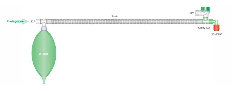
Mapleson F
Fresh gas flow for controlled ventilation: 100ml/kg/min
Mapleson F
Fresh gas flow for spontaneous respiration: 2L + 200ml/kg/min
Fresh gas flow for controlled ventilation: 1L + 1000ml/kg/min
Capnography
Principle: infra-red rays absorb CO2, but does not absorb O2. More CO2 absorption = High capnographic trace.
Main stream analyzer: the analyzer head is attached directly to the airway and the gas is analysed within the respiratory circuit through a clear window or cuvette.
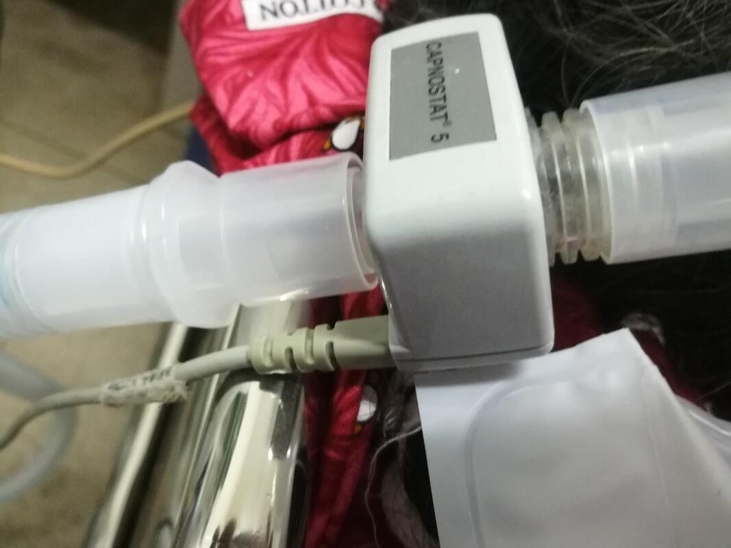
In the ICU where inspired gases are often humidified actively, mainstream may be more reliable than sidestream capnography.
Sidestream analyzer: describes the technique of continually aspirating a sample of gas from the respiratory circuit which is then fed through the analyzer.
Sidestream analyzer: describes the technique of continually aspirating a sample of gas from the respiratory circuit which is then fed through the analyzer.
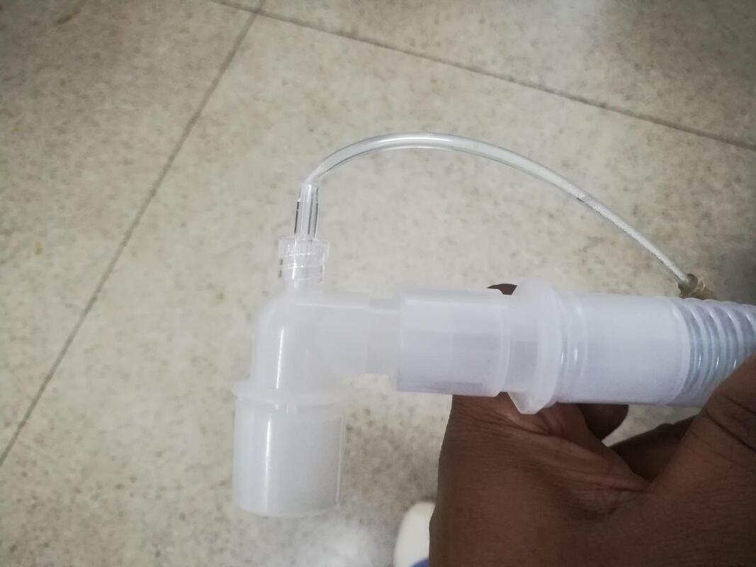
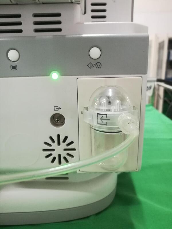
Sidestream capnography is favoured during anesthesia owing to the convenience of a light weight attachment to the airway, but may be troublesome due to sampling line blockage by water vapour following protracted use.
AMBU bag
Syringe pump
Defibrillation & Cardioversion
